AES3
Introduction
AES3 is a standard protocol for the exchange of digital audio signals between professional audio devices, also known as AES/EBU. AES3 was jointly developed by the Audio Engineering Society (AES) and the European Broadcasting Union (EBU). The standard was first published in 1985 and was revised in 1992 and 2003. AES3 has been incorporated into the International Electrotechnical Commission's standard IEC 60958, and is available in a consumer-grade variant known as S/PDIF.AES3 on Wikipedia
One aim developing the AES3 standard was to allow for the reuse of cable networks established for analog audio signal transmission for digital data transmission. These networks are often hunderds of kilometres long in facilities as broadcast studios. To transmit digital signals over these balanced, analog audio cables some conditions had to be met, which 'shaped' the AES3 standard.More background information
Specifications
An AES3 signal can carry 2 channels of PCM audio over several transmission media including balanced lines, unbalanced lines, and optical fiber. In total, four different kinds of physical interconnection types are defined by the IEC 60958 standard, three of which are in common use. Only type 1 is defined as a professional audio protocol, all other types often used in consumer audio installations. Types 2 till 4 are often called S/PDIF connections.
IEC 60958 Type 1 - Balanced XLR
This type is often used in professional installations and are considered the standard connector for AES3 protocol. The XLR cable should be a 3 conductor with a 110-ohm twisted pair cabling with XLR connectors. Note that the 110-ohm impedance of the cable is very important for maintaining signal integrity. Connector should be from end to end, male-to-female XLR.
IEC 60958 Type 2 - Unbalanced RCA
Type 2 uses an unbalanced, 75-ohm, 2-wired coaxial cable with RCA connector. Note that the cable should be coaxial, not a standard unshielded 2-wired cable, otherwise you would not maintain the required 75-ohm cable impedance. Again, if the 75-ohm impedance is not maintained, signal loss will occur. Connector should be from end to end, male-to-male RCA.
IEC 60958 Type 3 - Optical fiber F05/TOSLINK
Type 3 uses an optical fiber with F05 connector. The cable is usually plastic, but can also be made of glass. Other commonly name for this cable is TOSLINK. TOSLINK is usually found in television as a digital output. Connector should be from end to end, male-to-male F05/TOSLINK plug.
IEC 60958 Type 4 - Coax BNC
The last type of commonly used connector is the coaxial BNC cable. This type uses a 75-ohm coax cable with at the end a BNC connector. This type is commonly used in the broadcast industry, and not in the consumer or professional audio. It specially created for long distance runs.
Signal Terminator
A signal terminator is intended to consume the remaining energy of the signal at the end of the cable.
AES is an electrical signal, the energy of which is consumed at the end of the cable. However, not all energy is consumed. If this energy is not consumed properly it is reflected back into the cable. That reflection interferes and distorts the original signal. This can cause the 8c('s) to "lose" the signal and stop playback. To prevent this reflection from happening, the remaining, unconsumed, energy of the signal as to be absorbed by a so-called "AES-terminator", which is basically a resistor.
The correct amount of resistance in the termination is dictated by the resistance of the source or cable impedances. For the AES protocol this resistance is 110Ω.
Using AES3 with your 8c's
There are multiple ways to connect AES3 or S/PDIF sources to your 8c's. Below are supported setups. The 8c up to serial number 2000 supports PCM up to 96 khz / 24 bits on its digital AES3 input, serial numbers above 2000 supports PCM up to 192 khz / 24 bits on its digital AES3 input.
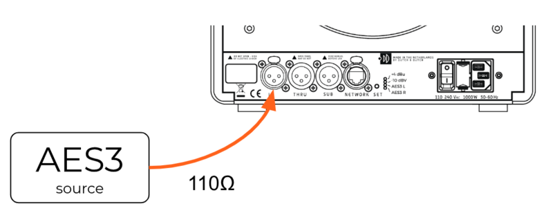
Single 8c
Use a balanced 3-conductor cable of 110-ohm twisted pairs cabling with XLR connectors.
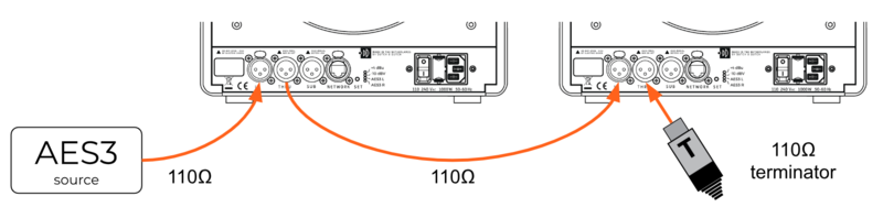
Stereo 8c setup
Use a balanced 3-conductor cable of 110-ohm twisted pairs cabling with XLR connectors. There should be one cable between the source and the shared analog and digital input of the first 8c. There should be a second cable between the first 8c’s THRU output and the second 8c’s shared input. Use an AES3-terminator (supplied with every pair of 8c’s) on the THRU output of the last 8c in the chain.
In the Dutch & Dutch app, go to settings for each individual 8c in the system. Set the placement of each 8c correctly, i.e. left for left and right for the 8c on the right.
Using S/PDIF with your 8c's
The correct way of using the 8c's with an S/PDIF output, is by means of an impedance transformer.